


Anatomy of a Dust Collector
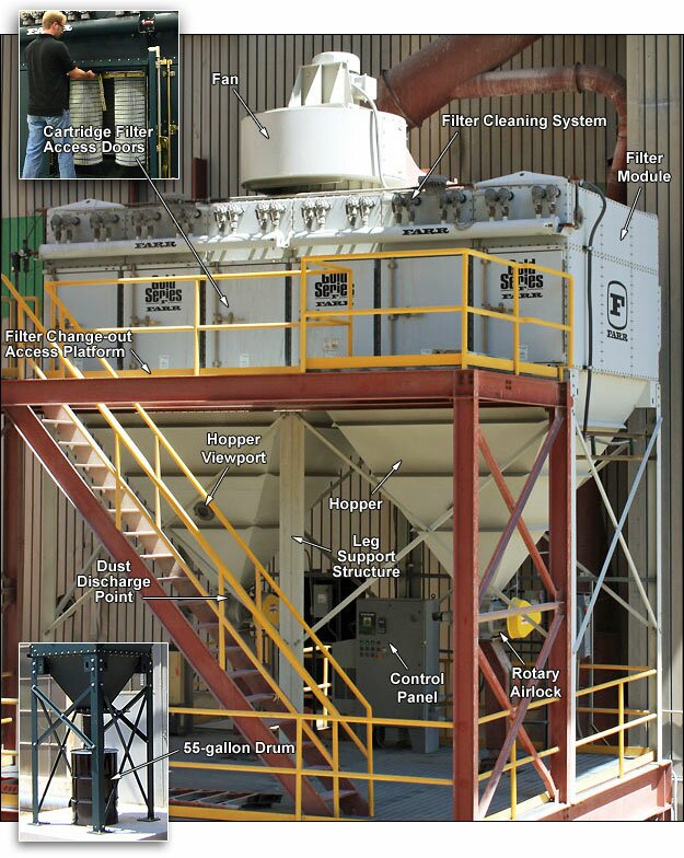
Filter Module
Upper part of the dust collector housing that contains the cartridge filters, filter access doors and filter cleaning system (compressed air reservoir, purge pipes, solenoid and diaphragm valves).
Hopper
Lower part of the dust collector that funnels dust that is captured in the collector down into a disposal channel or device. In the photo above, collected dust is discharging through a rotary airlock and down into a large, common bin on a lower level. 208 litres drums are common discharge devices that connect directly to the hopper with a flexible hose.
Leg Support Structure
Supports the entire dust collector housing. Typically designed for seismic 5 KMH and 161 kilometers/hour wind load.
Control Panel
Filters are automatically back-flush cleaned with periodic pulses of compressed air, typically through an on-demand setting in the electronic control panel. The control panel sends signals to solenoid valves, which trigger powerful blasts of air from the compressed air reservoir through diaphragm valves.
Fan
The typical arrangement of the fan (sometimes called a blower) is to pull air through the dust collector, creating a suction to draw dust into the filter module. The fan can be mounted on top, or remotely from the dust collector via ductwork.
Cartridge Filter Access Doors
Tool-less quick-open access doors to super-fast cartridge filter change-out system that does not require entry into the dust collector. Cam-operated clamp bars provide filter clamping and sealing.
Follow. Connect. Watch. Learn.